| Criteria | Acceptable Standard | Defective Standard |
| Component Placement |
1. All components correct as per BOM and assembly drawing (value, size, P/N). 2. Polarity and orientation correct. 3. Markings legible. No physical damage, cracks, or oxidation. |
1. Wrong part, missing part, wrong orientation, or reversed polarity. 2. Cracked, chipped, or damaged component body. 3. Severe oxidation or contamination on terminations. |
| Solder Quality |
1. Solder joints are smooth, bright, and concave with good wetting. 2. Solder covers ≥75% of the termination or pad. 3. No cold solder joints, non-wetting, or dewetting. 4. No solder bridges (shorts) between adjacent leads/pads. 5. Minimal, non-activated, non-ionic flux residue (if no-clean process). Residue should be thin, transparent, and non-tacky. |
1. Cold solder joint, non-wetting, dewetting (dull, grainy, porous appearance). 2. Solder bridges between any conductors. 3. Solder balls (especially under BGAs, QFNs), particularly any >0.13mm in diameter. 4. Solder icicles or spikes. 5. Excessive, corrosive, or tacky flux residue. |
| FPC Condition |
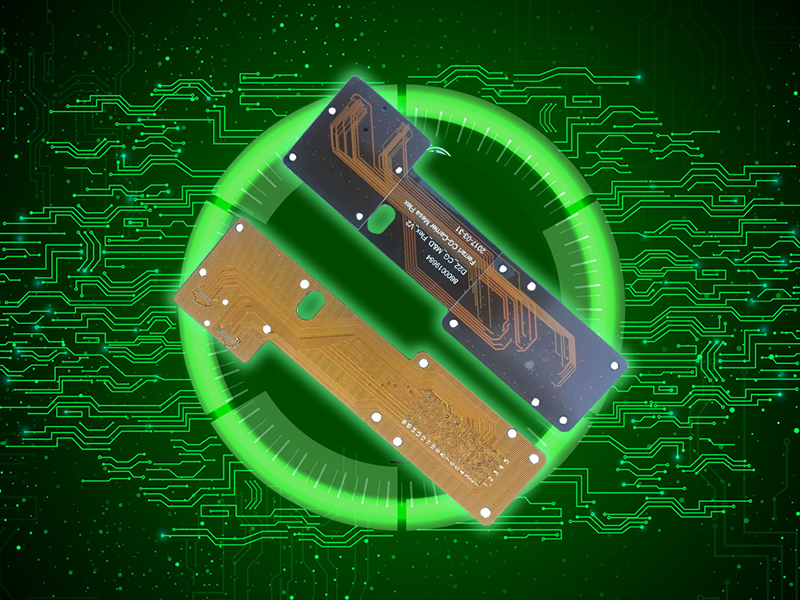
1. Gold fingers are clean, bright, free from scratches, oxidation, solder splash, or contamination. 2. Coverlay (Cover Coat) is intact with no blistering, delamination, or tears. 3. Pads are intact with no lifting or peeling. 4. FPC is not permanently deformed or creased (must lie flat in fixture). |
1. Gold fingers are scratched (exposing nickel/copper), oxidized, contaminated, or tarnished. 2. Coverlay is blistered, delaminated, or torn, exposing underlying copper. 3. Lifted or missing pads. 4. Sharp creases, folds, or permanent deformation of the FPC. |
| Adhesive/Shielding |
1. Adhesive (if used) is properly cured and adequately secures components without contaminating pads or contacts. 2. Shielding cans are seated flat and soldered securely on all sides. |
1. Uncured or insufficient adhesive. 2. Adhesive contamination on solderable surfaces. 3. Shielding can is warped, lifted, or improperly soldered. |
| Criteria | Acceptable Standard | Defective Standard |
| Continuity (ICT/FCT) |
1. 100% pass on In-Circuit Test (ICT) and/or Functional Test (FCT). 2. All networks correct—no opens or shorts. |
1. Test failure: opens or shorts. 2. Component values (R, L, C) outside specified tolerance. 3. Integrated circuits (ICs) fail functional test. |
| Insulation Resistance | Meets product specification. Typically ≥100MΩ @ specified voltage (e.g., DC500V) between high-voltage nets. | Insulation resistance below specified requirement. |
| Withstanding Voltage (Hipot) | Meets product specification. No breakdown or arcing at specified test voltage (e.g., AC1500V or DC500V for 60 sec). | Electrical breakdown, excessive leakage current, or arcing during test. |
| Criteria | Acceptable Standard | Defective Standard |
| Component Height | All components conform to the assembled height restriction, especially if housed in an enclosure. | Component height causes mechanical interference with the housing or other parts. |
| Component Misalignment |
1. Chip Components (C, R, L): Misalignment ≤50% of component width or pad width (whichever is less), with good wetting. 2. ICs (QFP, BGA, QFN): Misalignment ≤25% lead/terminal width. All leads must have contact with the land. |
1. Misalignment causes reduced electrical clearance or risk of shorting. 2. Terminals of bottom-terminated components (BTCs) like BGAs are off the pad. |
| Tombstoning | None. |
By continuing to use the site you agree to our privacy policy Terms and Conditions.