Views: 1619Author: Site EditorPublish Time: 2023-05-25Origin: Site
With this surge in usage of flex, the standards for rework (replacing devices while still meeting the initial specification and functionality) and repair (repairing the physical damage on a flex circuit) of these type of electronic interconnection circuits has not kept pace.
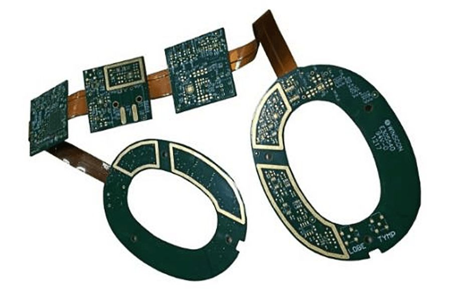
There are some rework challenges that come from the very nature of flex circuits. First of all, it is difficult to hold the flex circuitflat. The flexible nature of the Kapton or other base flex material, which makes it so attractive in the application, makes it challenging from a rework perspective. In order to retain the flatness of the assembly, it needs to be taped to be held down. In some cases, a vacuum fixture, a relatively pricey endeavor, is fabricated for flex circuit rework. When placing fine pitch components, the vacuum structure of such fixtures has a significant influence. If the vacuum is directly under some of the leads of a fine pitch component, there is a likelihood any vacuum will “pull” the flex into the hole, preventing the component from contacting the flex circuit lead, thereby resulting in an electrical “open.” For rework paste printing, co-planarity is a challenge when the stencil and surface to be printed are not coplanar. Therefore, paste print deposition using a syringe is often used instead. Sometimes, conductive epoxies are used in interconnecting devices to the flex material. While the curing temperature of these joining materials is much lower than the reflow temperature of more standard solder, it can make a mess. Even when the rework process is engineered properly, many times the limitation on rework is that the marginal cost of the assembly is far less than the burdened rework cost, making the scrap pile a more attractive economic alternative.
There are some advantages to reworking flex circuits from a process standpoint. The lower thermal mass compared to a rigid PCB shortens the duration time to reach liquidus when soldering to a flex board. This speeds up the rework process for replacement. In addition, many times this lowers the air temperature required from the hot air system thereby resulting in less potential component damage. The high temperature withstand properties of flex materials such as Kapton, Peek and high-temperature polyimide all give the flex rework process a larger process window.
In terms of industry standards for PCB repair, the IPC 7711/21 Repair and Modification of Printed Boards and Electronic Assembliescovers the rework and repair processes for flex circuits. Each of the processes in the standard are listed in terms of their applicability to flex rework or repair with an “F” in the upper right-hand part of the process documents under the “Board Type” section heading. There is even a flex-specific standard of conductor repair. Conductor repairs on flex is covered.
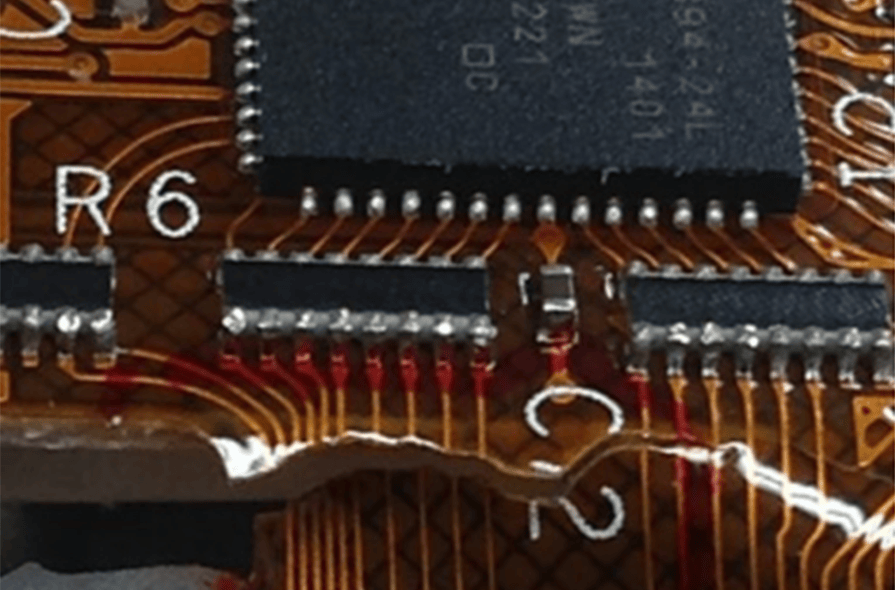
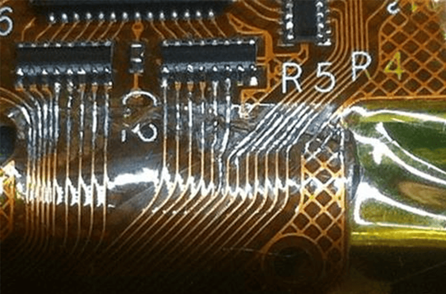
By way of an example of a conductor repair, the above figure illustrates a torn flex circuit as part of a rigid-flex board. The standard process found in IPC 7721 3.5.1 was used to repair the material. The conductor runs had a copper foil jumper installed to replace the damaged conductors and then they were soldered together for further rigidity. The outcome of this repair can be found in the below figure.
Rework and repair of flex circuit assembly is evolving and remains a challenge as the industry continues to adopt best practices from the rigid assembly world.